Home
Quickstart Guide
Introduction RIO Academic RIO Application examples Your first RT app Your first FPGA app
Real-Time
Basic procedures System admin File system I/O monitor System controller architecture Timed loops Inter-process communication RT/Host communication RT/FPGA communication FPGA personalities Interrupts Datalogger (file I/O)
FPGA
Design flow Simulation Inter-process communication RT/host communication Derived clock domain IP blocks FPGA personality
Networking
Get connected Email Web services UDP TCP IP addresses
Site Map
Guides Code examples Procedures Tags LabVIEW block diagram elements Targets Communications All pages
Glossary How to use About
RIO Developer Essentials Guide for Academia

Site map: Code examples

The PC VI interacts with the FPGA VI in simulation mode to apply a test sequence as the FPGA VI input and monitor the resulting output sequence.
Use a derived clock domain to effectively speed up or slow down the FPGA's 40-MHz clock for a selected portion of the FPGA block diagram.
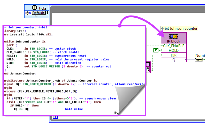
Reuse existing and validated VHDL-based circuit functionality in the FPGA block diagram instead of developing new LabVIEW G code to implement the same functionality.
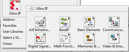
Configure and use Xilinx IP (intellectual property) modules designed specifically for the Xilinx Zynq FPGA
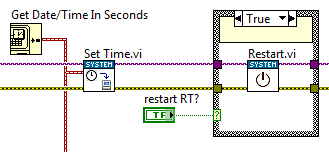
Use the "Set Time" function to adjust the RT system time to match the (assumed accurate) PC system time. Restart the RT target to save the current RT time to be reloaded on each reboot of the Academic RIO Device.
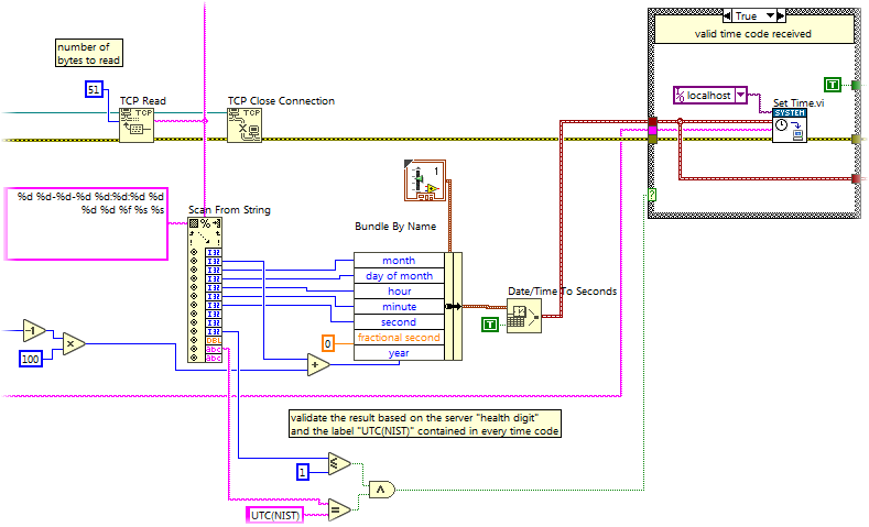
Synchronize the system clock time based on querying the Internet Time Service (ITS) maintained NIST (National Institute of Standards and Technology): Open a TCP/IP connection to the "Daytime Protocol" port 13, read the 51-character string, parse the string for time and date information, validate the result (look for a server health indicator and a "magic string"), and then adjust the system time.
Monitor process variables and sensor measurements, timestamp them, and log them to a file, and then remote access the datalog file through the network with WebDAV, web browser, or VI running on a PC host.

Timed loop
RT code

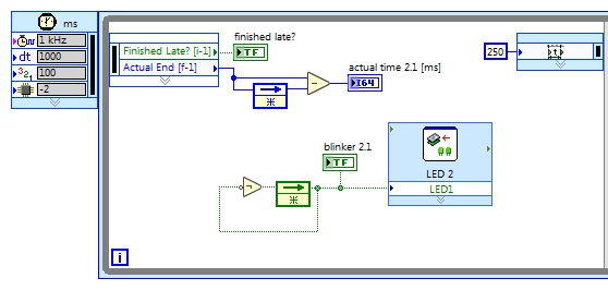
Use the "Timed Loop" to create a deterministic process loop, i.e., a loop that runs with a precisely-defined time per iteration.
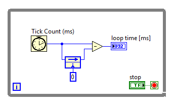
Use the "Tick Count" function to measure the total elapsed time per iteration of a process loop.
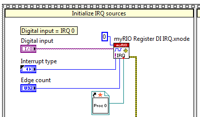
Run a callback VI each time that a digital input transition or an analog input voltage threshold crossing generates an interrupt request (IRQ).
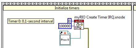
Run a callback VI each time that an FPGA-based interval timer generates an interrupt request (IRQ).
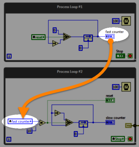
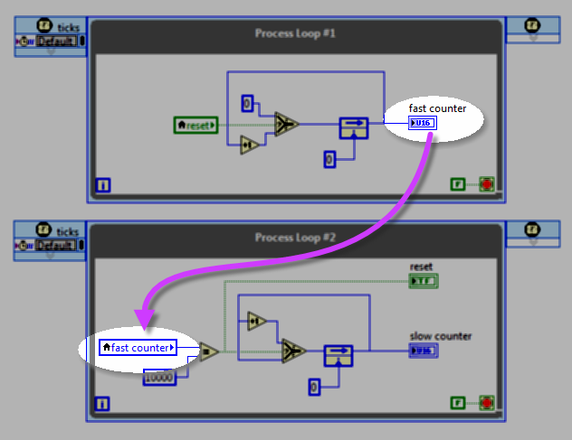
Use a local variable (front-panel indicator) to communicate between two parallel process loops contained within the same VI, and use a local variable to stop parallel loops with one "stop" button.
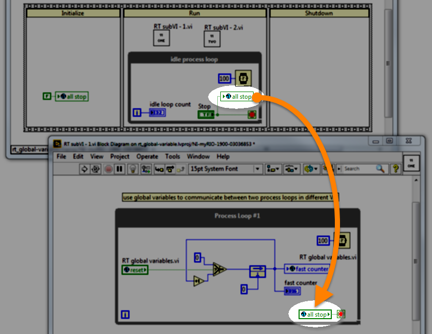
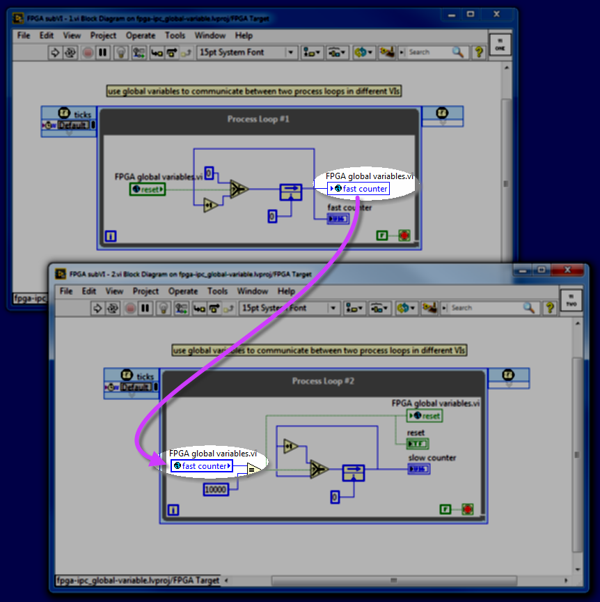
Use a global variable to communicate between two parallel process loops contained within different VIs under the same target, and use a global variable to stop parallel loops with one "stop" button.
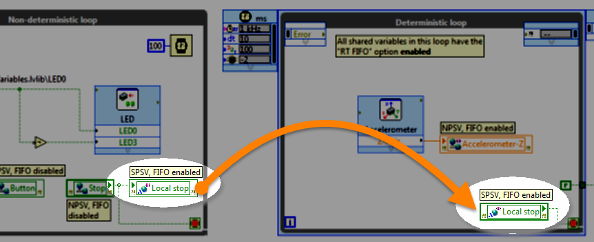
A single-process shared variable (SPSV) behaves like a global variable that links deterministic and non-deterministic process loops, effectively shielding the deterministic loop from elements that contribute jitter.
Use a functional global variable (FGV) to communicate between two parallel process loops contained within different VIs under the same target, and use a FGV to stop parallel loops with one "stop" button. The "functional" nature of the FGV means that you can create additional functionality beyond that of a basic global variable, e.g., counting and calculations that operate on the stored value.

Queue
RT code
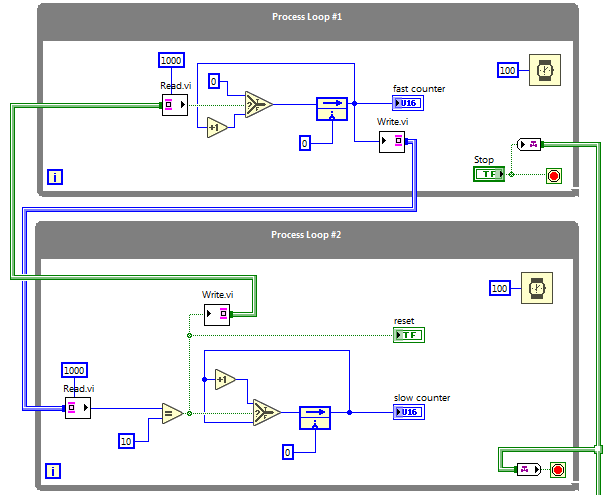
Use a queue to send messages and data between two or more parallel process loops contained within a VI or other VIs. Queues also serve as the foundation for the "Queued State Machine" design pattern.

Channel wire
RT code
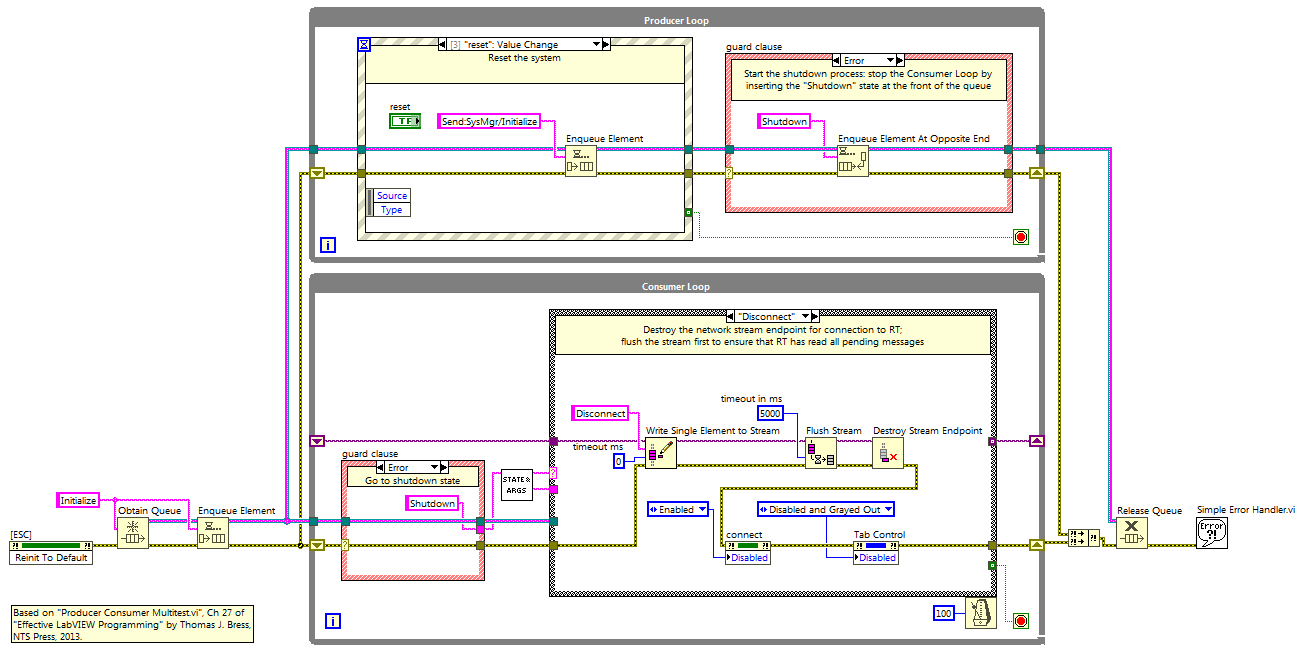
Use a channel wire to communicate between two (or more) parallel process loops contained within the same VI, and use a channel wire to stop parallel loops with one "stop" button. Requires LabVIEW 2016 or later version.
Use a local variable (front-panel indicator) to communicate between two parallel process loops contained within the same VI.
Use a global variable to communicate between two parallel process loops contained within different VIs under the same target.
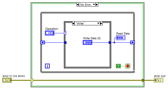
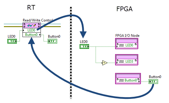
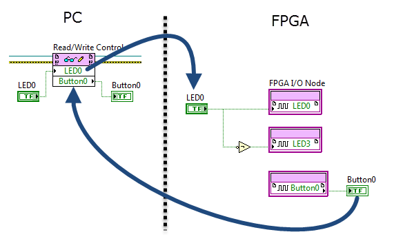
The RT VI operates (writes) the front-panel controls of the FPGA VI and reads its indicators.
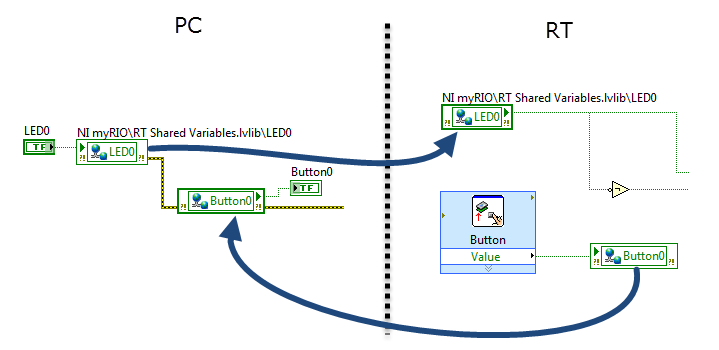
A network-published shared variable (NPSV) behaves like a global variable that links process loops residing in two or more network-connected targets.
Use the NPSV programmatic API (application programmer's interface) VIs as an alternative method to a shared variable node.
Send command and status messages through a low-latency lossless network-based data communication channel between the RT target and PC host system.
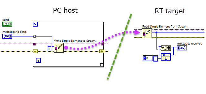
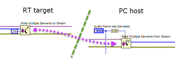
Efficiently transfer blocks of data between the RT and PC by network streams.
Efficiently transfer blocks of data between the RT and FPGA by direct memory access (DMA) first-in first-out (FIFO) buffers.
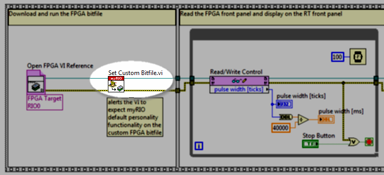
Load and run a modified version of the default Academic RIO Device personality (FPGA bitfile) augmented by user-defined functionality, for example, to make a high-precision measurement of pulse width.
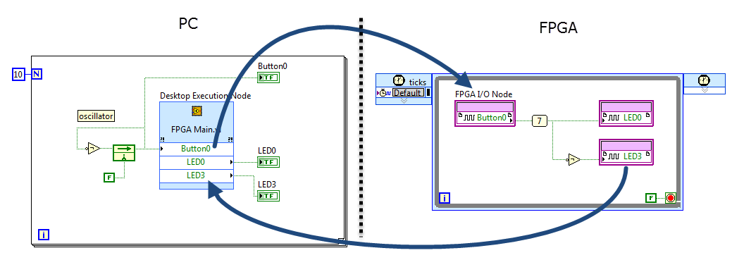
The PC VI operates (writes) the front-panel controls of the FPGA VI and reads its indicators.
Efficiently transfer blocks of data between the PC and FPGA by direct memory access (DMA) first-in first-out (FIFO) buffers.
State machines perform system control, data processing, and any task that involves executing a sequence of activities in response to inputs from the surrounding physical system, the user interface, and other processes within the system. The queued state machine is a particular implementation style that is flexible and versatile, easy to maintain, and computationally efficient.
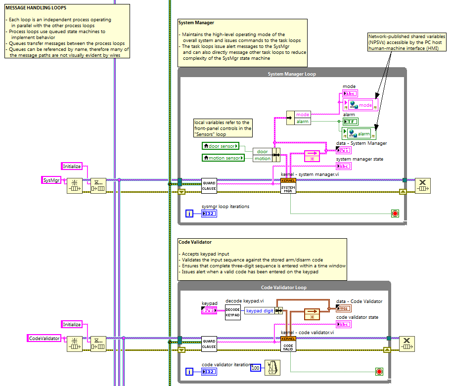
The queued message handler contains multiple process loops operating independently and in parallel that communicate with each other by sending messages through queues. Each process is a well-defined task implemented by the "Queued State Machine" design pattern. Breaking up the system into self-contained tasks greatly simplifies the design of complex systems.
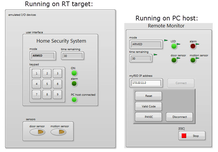
Example of a complete RT system controller based on the Queued Message Handler (QMH) design pattern with multiple parallel task loops implementing behaviors with queued state machines (QSMs), various inter-process communication techniques (queues and local variables), and inter-target communication techniques (network-published shared variables (NPSVs) and network streams). The PC host human-machine interface (HMI) can remotely connect to the system through the network, monitor the status of the security system, and control it remotely.
Create a responsive user interface based on two loops operating in parallel: the "producer" loop event structure responds immediately to user interactions such as button clicks and mouse movements that send commands through a queue to the "consumer" loop which performs the required tasks. Separating the state machine into two loops allows the user interface to remain responsive should a consumer task require an unusual amount of time or must wait for a shared resource to become available.

Show available IP addresses
RT code PC code

Display all of the network IP (Internet Protocol) addresses at which the RT target or PC host can be reached.
Use the Simple Mail Transport Protocol (SMTP) to send an email message; send the email to an SMS (Short Message Service) gateway service to forward the email as a text message.
Use the low-level Simple Mail Transport Protocol (SMTP) VIs create an email, attach a file, and set the email header to flag the message as 'high priority' in the recipient's email application. The illustrative application example captures webcam images at regular intervals and sends them as email attachments.
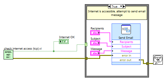
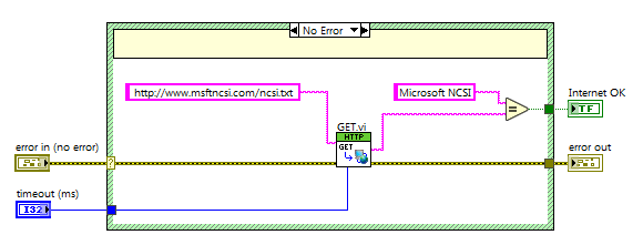
Determine whether or not Internet access is available by attempting an HTTP connection to the "Microsoft Network Connectivity Status Indicator" (NCSI) web service.
Determine whether or not Internet access is available by attempting a TCP connection to the "Microsoft Network Connectivity Status Indicator" (NCSI) web service.
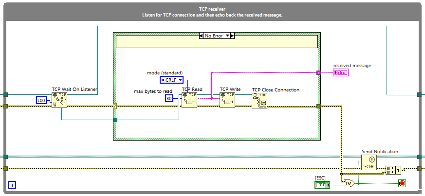
Send TCP/IP messages to a destination IP address and port number, listen for incoming TCP/IP messages on a user-defined port, and echo received messages back to the source. Combine the sender and receiver into a single "TCP ping" application to test the communication channel between two network hosts, and illustrate the notifier method to stop parallel loops with one "stop" button.

TCP client-server
RT code PC code
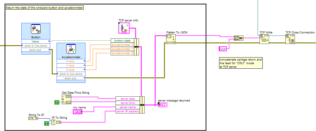
Create a server on the Academic RIO Device that listens for TCP/IP network connection requests from a client running on the PC host, accepts client information including the desired state of the four onboard LEDs, sets the LEDs accordingly, and returns the state of the onboard 3-axis accelerometer and pushbutton.
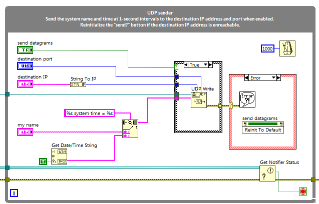
Send UDP messages to a destination IP address and port number, listen for incoming UDP messages on a user-defined port, and echo received messages back to the source. Combine the sender and receiver into a single "UDP ping" application to test the communication channel between two network hosts, and illustrate the notifier method to stop parallel loops with one "stop" button.

UDP client-server
RT code PC code
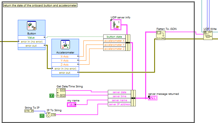
Create a server on the Academic RIO Device that listens for UDP datagram messages from a client running on the PC host, accepts client information including the desired state of the four onboard LEDs, sets the LEDs accordingly, and returns the state of the onboard 3-axis accelerometer and pushbutton.
Form a query string as a URL, retrieve the JSON string served by the Web service, and parse the JSON string to extract useful information.
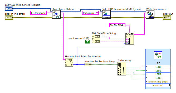
Host a web service on the Academic RIO Device to serve the states of onboard sensors (pushbutton and accelerometer) and system information (date, time, host name, and IP address), and to control the onboard LEDs based on a user-selected LED hex code.